Description
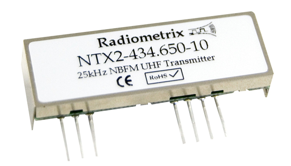
The NTX2 is a transmitter on the 434MHz frequency.
As seen in previous post, this frequency can be used without licence in
most of Europe.
NTX2 power is 10mW wich is authorised in the sky.
According to the documentation, NTX2 is supposed to transmit only to
500m, but with good line of sight, signal can be received from the sky at
more that 40Km.
NTX2 is transmiting by applying a voltage on it’s TXD pin.
Changing this voltage let us change a bit the frequency used to
transmit.
The module is factory-set to produce the specified FM deviation with a TXD input to pin 7 of 3V amplitude, i.e. 0V “low”, 3V “high
So we can apply some voltage on TXD pin to represent a 0 and another
voltage to represent a 1.
On the receiver side, we will see the frequency changing, and we will be
able to decode 1 and 0.
The “factory” frequency (for exemple 434.650 MHz) is around 1.2V applied on TXD pin (not 1.5V)
When applying a voltage < 1.2V the frequency will be under 434.650Mhz, and applying a voltage > 1.2V, the frequency will be above 434.650Mhz.
The NTX2’s TXD input is normally driven directly by logic levels but will also accept analogue drive (e.g. 2-tone signalling). In this case it is recommended that TXD (pin 7) be DC-biased to 1.2V approx.
As read on UKHAS, the
better “shift” seems to be around 500Hz.
If we want 500Hz between 0 and 1, we shoud apply a difference of 0.25V
on the TXD Pin.
FM deviation (peak) ±3 kHz
So we have 6KHz deviation for 3V range.
3V / 6000 = 0.0005V for 1Hz 500 × 0.0005V = 0.25V for 500Hz
So we can apply for exemple 2V for a 0 and 2.25V for a 1… (Or 1.25V
and 1.5V etc..)
GPIO / Serial
According to UKHAS members, it’s not possible to use a regular GPIO output on the RaspberryPi to properly shift voltage to the NTX2 TXD. The reason is the Raspberry is not “real time”, so you will successfully change voltage (output of GPIO and voltage divider), but the timing will not be accurate enough to successfuly decode packets.
The “trick” is to use a serial connection. The reason is the serial circuit has it’s own crystal that will produce an accurate timing.
Dave Akerman use the internal embeded
serial available on the Raspbery.
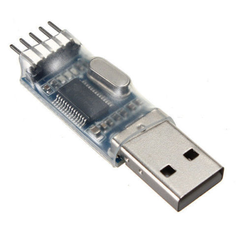
As I wanted to keep the embedded serial, available for control, I used a
Profilic PL2303 USB serial instead. This worked fine.
Note that the arduino has an accurate timing and don’t need the “serial” trick
Voltage divider
Output of the serial of the RaspberryPi is 3.3V level but output of
Profilic PL2303 could be AFAIK 3.3V or 5V level.
In both cases, we will need a Voltage Divider to have the 0.25V shift within the range 0 - 3V. For exemple we could have: Low level (0V) -> 2.38 V High level (5V)-> 2.63 V
See details on UKHAS wiki and see how to calculate resistors.
Using the serial device
Using serial is, I think, also nice, as we can easily sent data to the
serial device.. It will be automatically “coded” to 0 and 1.
So having the NTX2 transmitting “Hello wold” is just:
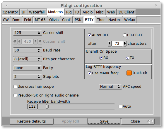
- Setting the RaspberryPi serial device to the correct settings (Baudrate, Bit par character, Parity, Stop bit):
man stty
- Sending the text to the serial device:
echo "Hello world" > /dev/serialDevice
On the dl-fldigi side, we can easily decode by setting the same serial
parameters into the RTTY tab